Serial FLASH Programming User’s Guide Version 30-Apr-2021 Introduction This manual describes the basic concept of serial Flash programming. How This Manual is Organized. Background Information: Provides information about important terms in serial Flash programming, such as SPI interface controller, block, and page. Programming SPI memory devices is a common use case for the Promira™ Serial Platform with SPI Active Level 1 Application. There are several ways to do this with the Promira™ Serial Platform, including using Control Center Serial, Flash Center, or the Promira API.
- I have a 3-wire serial programming interface (SPI) that controls an internal 32-bit shift register. There are a total of 3 signals that need to be applied: the clock (CLK, pin 47), the serial data (DATA, pin 46) and the latch enable (LE, pin 45). It has an additional pin (RDBK, pin 2) for read-back functionality. This pin is a digital pin and can be used to read-back values of different.
- TMS320C672x DSP Serial Peripheral Interface (SPI) This reference guide describes the TMS320C672x Serial Peripheral Interface Module (SPI). The SPI is a synchronous, full-duplexserial port which supports 3-pin,4-pin,and 5-pinoptions. Figure 1 contains a block diagram of the SPI module. The major SPI components are:.16-bitshift register (SPIDAT0).
I have a 3-wire serial programming interface (SPI) that controls an internal 32-bit shift register.

There are a total of 3 signals that need to be applied: the clock (CLK, pin 47), the serial data (DATA, pin 46) andthe latch enable (LE, pin 45). It has an additional pin (RDBK, pin 2) for read-back functionality.This pin is a digital pin and can be used to read-back values of different internal registers.

The DATA (DB0-DB31) is loaded LSB first and is read on the rising edge of the CLOCK. The LE isasynchronous to the CLOCK and at its rising edge the data in the shift register gets loaded onto the selectedinternal register. The 5 LSB of the Data field are the address bits to select the available internal registers.

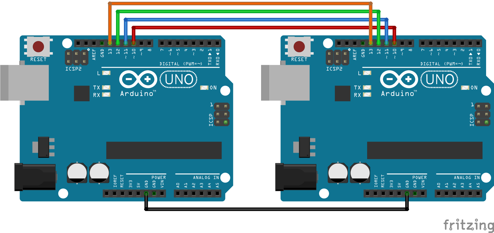
The Arduino Due and the SPI library are a 4 pin based (MISO, MOSI, SCK, SS). How should I connect the Arduino Due to my 3-wire-SPI device?
Spi Bus Protocol
Thank you very much.